Ultrasonic Testing
Ultrasonic Testing (UT) is a non-destructive testing method that uses high frequency sound to
conduct inspections


3angles offers Ultrasonic Testing on various turbine and generator components. Ultrasonic Testing offers high-sensitivity evaluation with very high consistency – this testing is especially beneficial for evaluating components that go through routine in-service inspections, such as bearings, fasteners, forgings, retaining rings, wheel discs, etc.
Principle of Ultrasonic Testing
High-frequency sound energy is used in ultrasonic testing (UT) to conduct inspections and measurements. For example, the ultrasonic inspection can be employed in dimensional measurements, material characterization, flaw detection and evaluation, and more. As shown below, a typical pulse/echo inspection configuration will be utilized to demonstrate the general inspection idea.
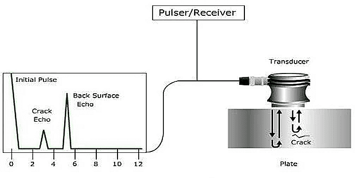
A typical UT inspection system is made up of several functional components, including a transducer, display, and pulser/receiver. An electronic device that generates high-voltage electrical pulses is a pulser or receiver. The transducer produces high-frequency ultrasonic energy under the control of the pulser.
Waves made of sound energy go through the materials after being introduced. A portion of the energy is reflected from the flaw surface when there is an interruption in the wave path (like a crack).
The transducer converts the reflected wave signal into an electrical signal, which is then shown on a screen. The figure above shows the strength of the reflected signal about how long it took for an echo to be received after the signal was generated. The signal's distance can be directly correlated with the signal travel time. It is occasionally possible to determine the position, size, direction, and other reflector characteristics of the reflector from the signal.
Techniques of Ultrasonic Testing
- Pulse echo/straight beam testing
Typically, single or dual crystal transducers are used in compression wave pulse-echo techniques to direct ultrasonic energy perpendicular or nearly perpendicular to the scanning surface. These methods are frequently referred to as "straight beam testing" methods.
- Angle beam
Using the angle beam approach, ultrasonic waves are sent into a test specimen at a specific angle to the test surface. The wave modes generated in the test specimen can be surface wave modes, transverse modes, or mixed longitudinal and transverse wave modes. To test angle beams, transverse wave probes are typically employed.
To discover flaws whose orientation is unsuitable for detection by conventional beam techniques, transverse waves at different angles of refraction between 35° and 80° are used.
Our applications of Ultrasonic Testing include:
- Ultrasonic examination of bearings
Ultrasonic detection of lack of bond between babbitt metal and the base material supporting the babbitt metal of journal and thrust bearings. The ultrasonic examination for lack of bond of babbitt metal is based upon observing the loss of sound transmission at the interface of the babbitt and base metal in the area of lack of bond. In addition, the normal reflection pattern from bonded babbitt is decreased in amplitude or absent altogether depending upon the size of the area. Another technique used for detecting lack of bond is using the RF phase inversion technique.
- Ultrasonic examination of fasteners
Ultrasonic testing of bolts, studs, and fasteners. The primary objective of the testing is to detect service induced discontinuities that affect the integrity of the part.
- Ultrasonic examination of generator retaining rings
For this inspection we will utilize the Automated Inspection of Retaining Rings (AIRR) system. The AIRR system is equipped with ultrasonic (UT) and eddy current (ET) transducers. The ultrasonic measurements inspect the ring ID with emphasis on the shrink fit areas and wall thickness steps. ET is used to inspect the OD surfaces.
The objective of the examination is to find indications that could be associated with arcing, fretting, intergranular stress corrosion cracking (IGSCC), or other in-service induced indications that may be present. The examination includes reporting conditions such as oil uptake that can transport contaminates to ID surfaces of the rings as well as visual conditions such as hot spots and physical damage.
- Ultrasonic examination of bores in turbine and generator forgings
During a boresonics examination, we introduce sound beams into the rotor material from the surface of the bore to detect reflectors which represent flaws in the rotor volume. The Ultrasonic inspection is performed moving the appropriate ultrasonic search units through the length of the rotor bore and recording the observed specular reflectors emanating from flaws facets or boundaries. This process is accomplished by utilizing a motorized scanner that moves the ultrasonic search units through the length of the rotor bore.
- Ultrasonic periphery and axial examinations of turbine and generator forgings
Ultrasonic examination from the peripheral surfaces of turbine/generator rotors and large steel forgings. Because the solid rotor is boreless, ultrasonic methods must be deployed that utilize to OD periphery surface as the inspection surface to perform a volumetric examination. Depending upon the complexity of OD geometry, the extent of volumetric coverage will generally be less comprehensive than inspection performed on a bored rotor forging using boresonics.
- Ultrasonic examination of blade attachments and disks on turbine shafts (Wheelsonics)
Wheelsonics is a series of examinations that may be performed on different turbine rotor configurations. Our capabilities include:
➢ Tangential blade attachment examinations
➢ Disk Bore and Keyway examinations
➢ Peripheral examinations