Magnetic Particle Testing
Magnetic Particle Testing (MT) is a nondestructive testing method of revealing surface and subsurface discontinuities in magnetizable materials.
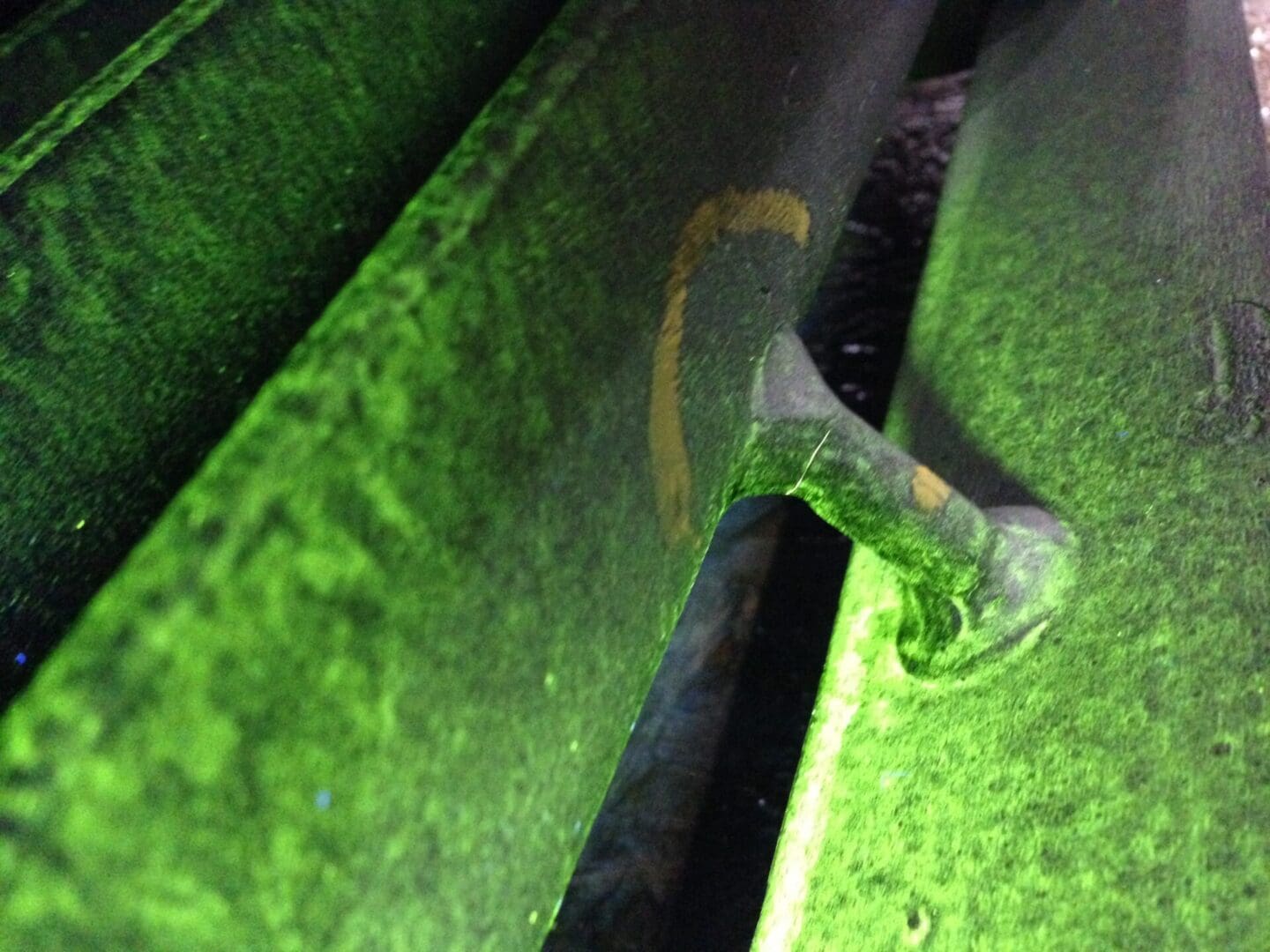
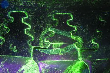
This is accomplished by inducing a magnetic field in a ferromagnetic material and then applying the surface with iron particles (either dry or suspended in a liquid). Surface and near-surface flaws disrupt the flow of the magnetic field within the part and force some of the field to leak out at the surface. Iron particles are attracted and concentrated at sites of the magnetic flux leakages. This produces a visible indication of defects on the surface of the material.
3angles performs Magnetic Particle Testing on the following components:
- Steam Turbine Rotors
- Generator rotors
- Diaphragms
- Blade Carriers
- Casings
- Studs and Nuts
- Shells
- Valve Components
The following are the various techniques we utilize for Magnetic Particle Inspections.
- Head Shot Technique
Using the head shot technique, current passes through the component creating a circular magnetic field allowing it to find indications in the axial direction. As an example, this technique is used for steam turbine rotor inspections. The size of the rotor will determine how much power is needed to create a magnetic field with sufficient strength. Depending on the size of the turbine rotor, a magnetization power unit that generates an adequate direct current output for the rotor is selected. The output of our portable power units ranges from 750 AMP to 10,000 AMP direct current. The highest direct current output is suitable to magnetize nuclear steam turbine rotors. For turbine rotors, the inspection of the tangential direction is accomplished by longitudinal magnetization using a 3-turn coil or bucking field.
- Coil Technique (Coil Wrap/Cable Wrap)
The coil technique uses a flexible insulated copper cable that can be turned into a 3-loop coil. The coil technique produces a longitudinal magnetic field and is often used for the inspection of larger parts. For steam turbine rotor inspections, for example, the coil is draped over a segment of a blade row to produce a longitudinal field (radial direction) in the blade section.
- Bucking Field
Bucking field is a magnetic flow technique configuration where poles of like polarity are induced on the ends of a test object to force magnetization into extremities that are normally field free. Using this technique for the inspection of steam turbine rotors, the rotor is wrapped with three (3) turns of cable in one direction on one side of a blade wheel and then wrapped with three (3) turns of cable in the opposite direction on the opposite side of the blade wheel. When using this wrapping process opposing magnetic fields are generated by each coil. The opposing fields in the blade wheel area between the two coils radiate out to the blade tips. This process produces a longitudinal magnetic field in the blades that can detect circumferentially oriented cracks.
- Portable Handheld Electromagnetic Yoke
The Yoke method is a technique that is widely used for localized inspections. The yoke has an electric coil in the unit that creates a longitudinal magnetic field that transfers through the legs to the examined part.
- Prod Method
The prod method uses two hand-held electrodes that are pressed against the surface of a part to enable a magnetizing current through the metal. The current passing between the two contacts creates a circular magnetic field around the electrodes which can find indications perpendicular to the magnetic field direction.
- Demagnetization (De-Mag)
Demagnetization methods are based on subjecting the magnetized part to a continuously reversing magnetic field that gradually reduces within the part. This can be performed using a reversing DC field; however, an AC field is a preferred method because this method can be accomplished by gradually reducing the applied current to zero or by passing the part through an AC demagnetizer. A complete demagnetization is hard to achieve; however, we aim to at least reduce the residual field to an acceptable level.
Demagnetization may be necessary for the following reasons:
- The part will be used where a residual magnetic field will interfere with the operation.
- The part will be machined, and chips may adhere to the surface being machined.
- Foreign particles may attract to the magnetized part and cause mechanical damage during operations.
- The part will be welded, and Arc blow may be caused due to the residual magnetic fields.
- Wet Bench Unit – Head Shot, Central Conductor, 5-turn coil
We also perform Magnetic Particle Testing on our wet bench unit which has the capability to magnetize parts using up to 5,000 AMPS DC. This unit is mostly used for the inspection of new machined parts and components. The unit has a set-up to perform a head shot, central bar, as well as using a 5-turn coil to magnetize parts.
Quantitative Quality Indicators (QQI’s)
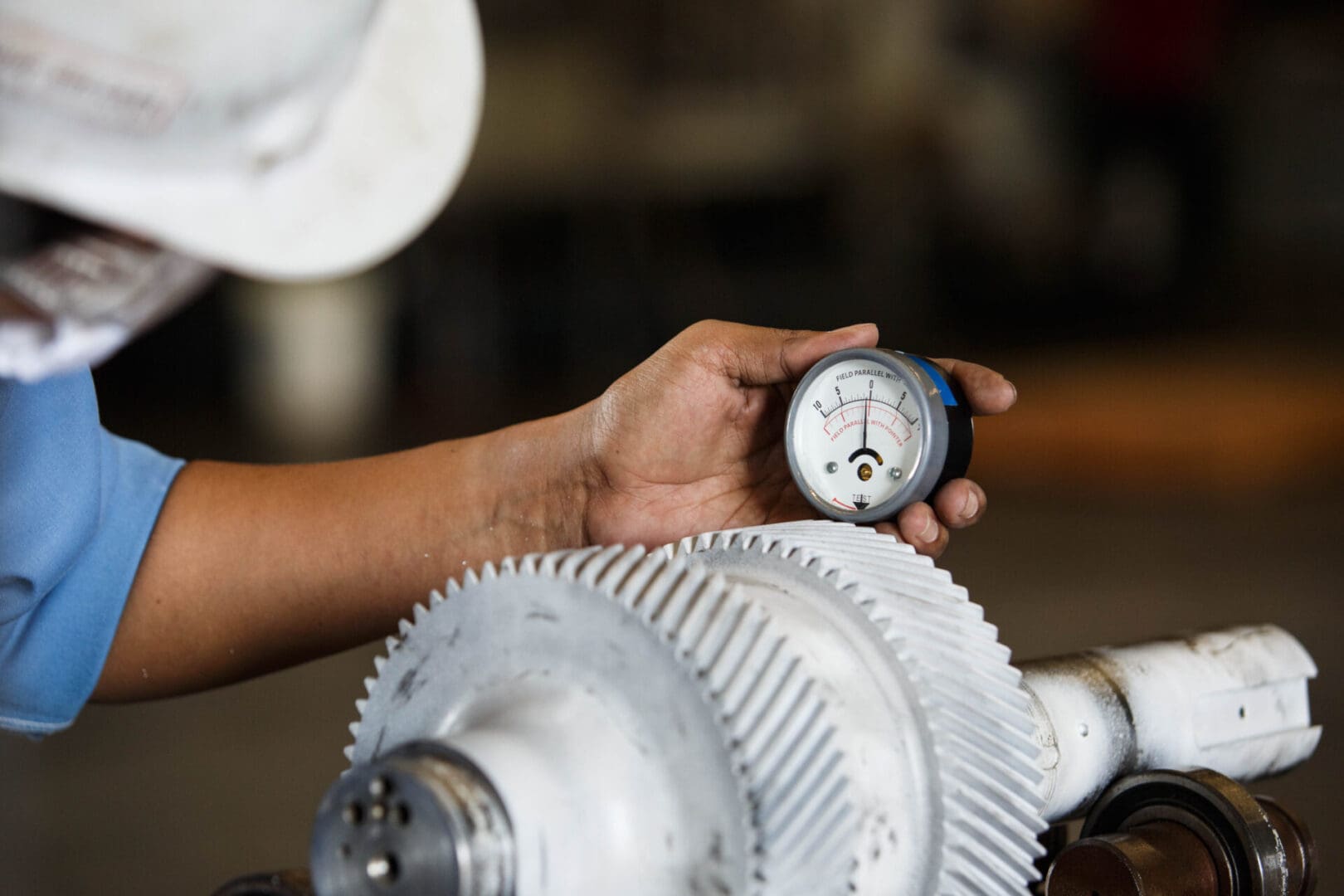
QQI’s are utilized when performing magnetic particle inspections to determine adequate field strength and field direction.


