Boresonics Inspection, Power Honing and Removal & Installation of Rotor Bore Plugs
BORESONICS
In a boresonic inspection, we look for indications in the forging of a rotor. Micro-inclusions, inclusion arrays, flakes, thermal cracks, forging cracks, porosity, shrink voids and pipe in stress concentration can initiate and grow cracks on a micro-scale. These flaws are the subject of concern and are the primary target of in-service boresonic inspection
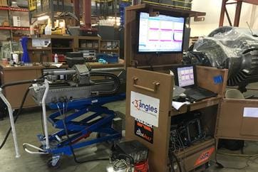
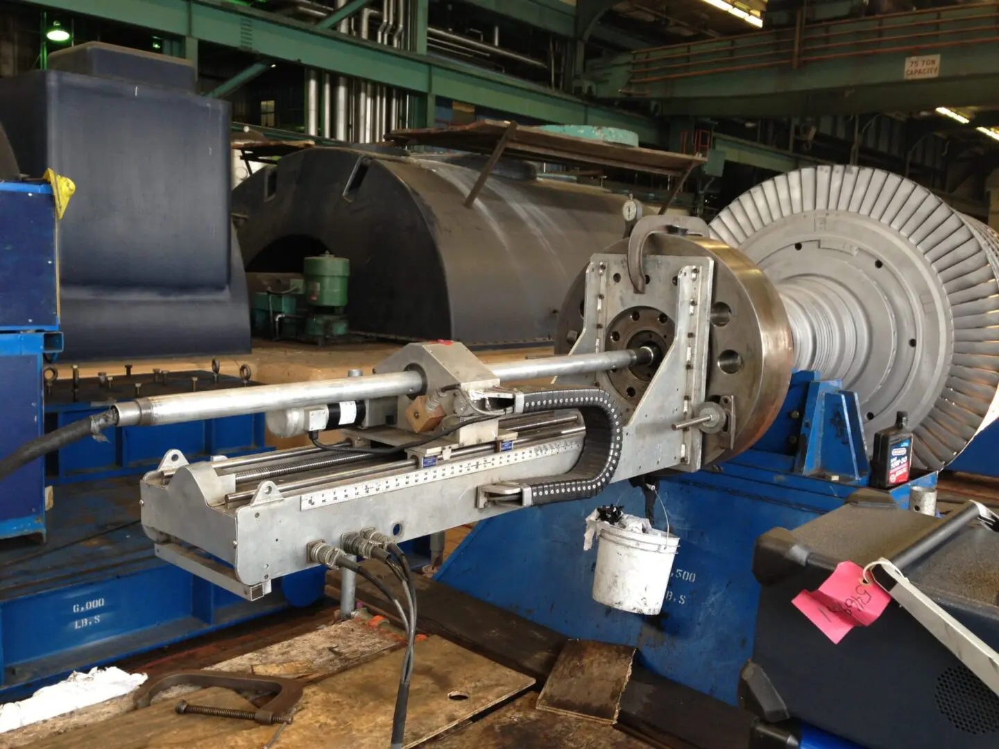
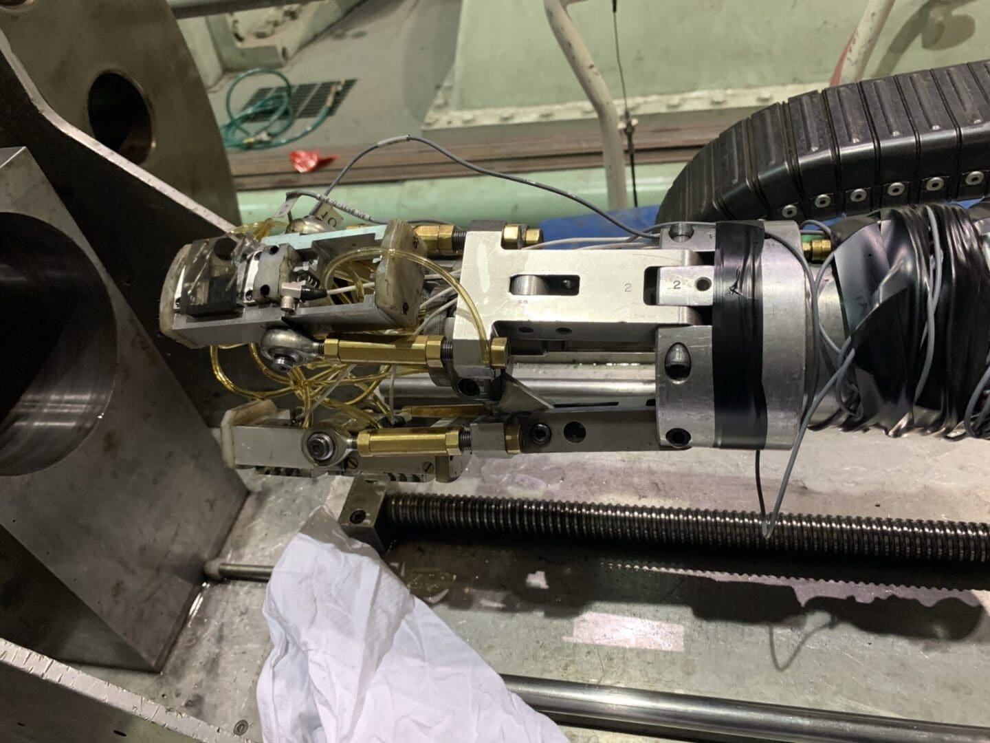
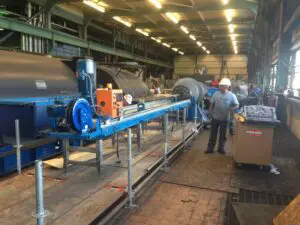
In boresonic examination, we introduce sound beams into the rotor material from the surface of the bore to detect reflectors which represent flaws in the rotor volume. An Ultrasonic inspection is performed which involves moving the appropriate ultrasonic search units through the length of the rotor bore and recording the observed specular reflectors emanating from flaws facets or boundaries. This process is accomplished by utilizing a motorized scanner that moves the ultrasonic search units through the length of the rotor bore. The ultrasonic search units are coupled with the bore by direct contact using oil or similar liquid as an acoustic couplant.
The data acquisition system then records the presence of ultrasonic reflectors in the rotor material in a format that allows for calculating the distance along the bore, radial distance from the bore surface, angular location, as well as the signal amplitude of the reflector. Flaw registration is thus accomplished using an amplitude-based detection method. A map of these reflector locations is plotted to define the overall distribution of flaw data detected in the rotor.
The objective is to detect, locate, and size flaws that have the potential for effecting the integrity of the rotor. This information can be used in an engineering analysis to determine if the flaw is critical to the reliability of the rotor.
Our comprehensive boresonic inspection includes:
- Removal of the bore plug and installation of its replacement plug
- Power honing
- Bore diameter measurements
- Bore-side nondestructive examination (NDE)
- Visual Inspection
- Magnetic Particle or Eddy Current Inspection
- Ultrasonic Inspection
- Engineering Evaluation
POWER HONING OF ROTOR BORES
Power honing is performed to efficiently remove the buildup of scale and/or oxidation from the bore surface that may form during in-service operation of the unit.
Typically, the honing process involves removal of 0.010” to 0.050” of material stock from the bore diameter. Rotors that have previously been subjected to power honing and show evidence of minimal oxidation may only require minimal stock removal to provide an acceptable surface finish of approximately 63 microinches (Ra).
Bore finish (or surface texture) parameters are directly related to the sensitivity of many NDT test that are performed to evaluate the condition of the rotor forging. Generally, the smoother the finish of the test surface the greater will be the sensitivity for detection of minute flaws within that tested material. Of all the applicable NDT methods, magnetic particle testing will benefit most in terms of flaw detection sensitivity given a smoother surface finish. However, since most providers of boresonic services employ a contact method of ultrasonic testing, a 63 microinch finish will be of benefit as well in regards to improved signal-to-noise ratios.
The 3angles power honing system covers bore diameters between 2.75" and 13".
Manual honing can be performed as well as an alternative to power honing. Typically, this light duty honing process involves removal of 0.005” to 0.010” of material stock from the bore diameter.
REMOVAL AND INSTALLATION OF ROTOR BORE PLUGS
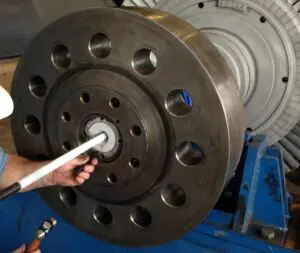
Before inspecting bored rotor forgings, the bore plug(s) will need to be removed as the inspections are conducted from the bore-side. Bore plugs have been installed in bored rotors to seal the internal cavity from the external ambient atmosphere. 3angles deploys two techniques for bore plug removal:
- Collapsing technique
- Machining technique
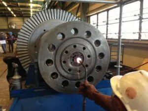
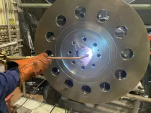
Applying the collapsing technique will collapse the bore plug and relieve the interference fit that holds the plug-in place. This process utilizes a drilling technique to structurally weaken the bore plug which will in turn yield to the stresses produced by thermal expansion when the plug is properly heated; combined with thermal differentials between the plug and rotor coupling. The machining or milling technique will machine the bore plug and reduce the material to chips, leaving a thin shell that can be extracted from the plug bore cavity without galling of the bore surface.
After the inspections have been performed new bore plug(s) will need to be installed. A bore plug provides a gas tight mechanical seal by incorporating an interference fit in the order of 0.0013 to 0.0015 inches per inch of bore diameter. For example, a 4.000” plug bore opening would receive a bore plug that is 0.006” larger than the bore opening. Therefore, the diameter of the plug must be reduced to allow insertion into the bore.
In general, bore plugs are shrunk in diameter by immersing the plug in a bath of liquid nitrogen. Since the steel plug has a positive coefficient of linear thermal expansion, it will contract linearly as the temperature of the metal is reduced. Given sufficient reduction in diameter, the cold plug may be inserted into the bore cavity and held in place until it expands due to heat transfer from the surrounding metal shaft. Plug installation by shrinkage of the plug alone is the preferred method. However, under some conditions the clearance between the shrunk plug and the bore opening may remain too tight for a safe insertion. In this case, it may be possible to gain additional clearance by heating the coupling flange to expand the bore diameter as well.

